
Why would we need a test stand?
In order to support our self mixed propellant program we need a way to test the performance of different mixtures. We simulate the performance of the experimental motors but due to factors outside our control, like the humidity in the air durring mixing, these simulations cannot perfectly represent the real world performance of the motors. This static test stand is designed to test the motors performance by measuring its thrust curve; which is thrust as a function of time. Because we are not a group with a large amount of money we wanted to keep it as cheap as possible.
Design and function
This test stand can be separated into two main portions, mechanical, and electrical.

Original Test Stand setup
The mechanical portion is made up of three support legs welded to a guider tube. This guider tubes inner diameter is slightly larger than 54 mm to allow us to place 58mm motors inside it to test. The guider tube also acts as a safety precaution. It is quarter inch thick and is made of a material so that if it failed during testing it would do so in a way that would not cause fragments but stay as one large, but now torn, piece. In order to use this test stand with 38mm motors a secondary sleeve was created with a 38mm inner diameter. This increases the thickness of the sleeves to half an inch. This makes testing smaller motors even safer. At the bottom of the guider tube there is a conical wedge to so that all the force is guided onto the force sensor. The three legs of the test stand are connected to each other using cross braces to increase frame rigidity. One additional cross brace was placed in the center to allow mounting of a cup to hold the force sensor. All connections on this test stand are welds. The inspiration behind the design of this test stand was drawn heavily from Richard Nakkas STS-5000 Static Test Stand.
My contribution to the building of the test stand came in doing all of the electronic potions of the data collection. We are using a force sensor that can measure up to ~890 Newtons. Originally I had built some amplification circuitry to allow an Arduino to be used as a data acquisition (DAQ) device. The Arduino would read the signal using its analog pins, time stamp it, and then write it to the laptop over a serial port. On the laptop I had a script that would collect the data and then store it. Afterword I had a script that would run through the collected data and automatically analyze. This script would determine things like burn time, total impulse, average force, and max force as well as create visual graphs of the thrust curve.

Test stand test burn
This functioned for a few months but I was told by a friend about programmable systems on a chip (PSOC). These are like microcontrollers with integrated analog components. I replaced the Arduino DAQ and amplification circuitry with a single PSOC which reduced the costs from ~$30 for the electronics to ~$10. The PSOC was also able to sample at a much faster rate then the Arduino. The Baud rate, from the serial communication, was the limiting factor in how fast we could collect data so I set the PSOC to over sample the sensor and send over the average of several samples.
Safety
This is real testing of experimental motors, safety precautions must be taken. Things can and will go wrong. Our safety precautions were
- To get our campuses environmental health and safety’s approval
- To get campus police’s approval and then to alert them to testing before every test burn.
- To maintain a 200 foot distance away from the test stand while testing
- To have only one person near the test stand during loading the motor
- To have 1 arming switch and 1 arming key turn before the ignition button was activated.
- To wait at least two minutes since the last visible sign of smoke before we approached the motor.
- To give a motor/igniter that did not ignite a 5-10 minute cool down before we approached it.
Validation of the test stand
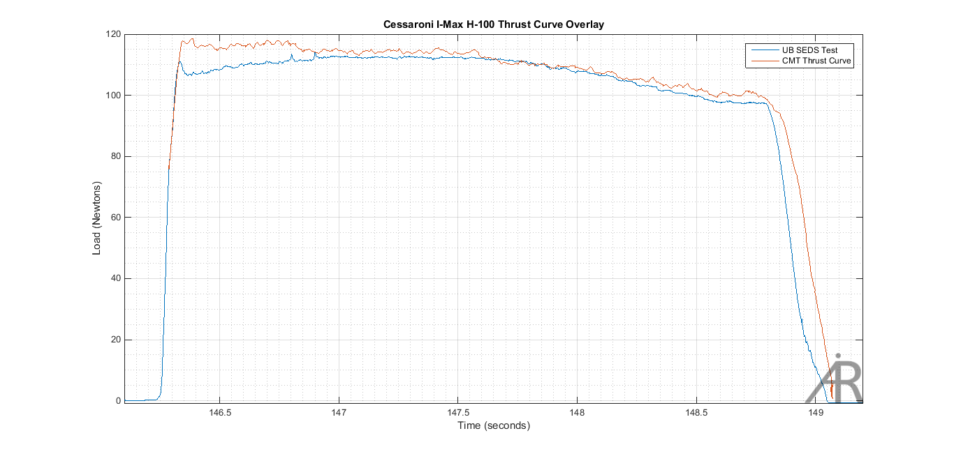
In order to validate all components of the test stand we tested a Cessaroni H-100 I-Max motor on the test stand and compared it to the manufacturers own test of the motor from 2009.
- Max force
- Manufacturer Data – 117.9 Newtons
- Test stand Data- 112.80 Newtons
- Total impulse
- Manufacturer Data – 286.4 Newton Seconds
- Test stand Data- 282.49 Newton Seconds
- Burn time
- Manufacturer Data – 2.82 seconds
- Test stand Data- 2.8 seconds
Because we tested in 2017 we expected some changes between the batch the manufacturer tested and the batch our motor came from but we consider all the measurements to be close enough to have full faith in our test stand.
The thrust curve is shown below with our curve being in blue and the manufacturers curve plotted in red.
Final notes on test stand performance
- Sampling frequency ~ 600 Hz
- Oversampling = 47
- Max force ~ 890 Newtons
- Resolution ~.24 Newtons
Future improvement
I’ve avoided posting any schematics or code here as I still want to make a few upgrades to the test stand. Mainly I think I can increase the resolution and the sampling frequency while reducing the oversampling rate by improving the efficiency of the data transferred over the serial line and reducing the number of over sampled points.